

Produsen Custom Global, Integrator, Consolidator, Mitra Outsourcing kanggo Macem-macem Produk & Layanan.
Kita minangka sumber siji-mandeg kanggo manufaktur, fabrikasi, teknik, konsolidasi, integrasi, outsourcing produk & layanan sing digawe khusus lan ora kasedhiya. Kita uga label pribadi / label putih produk sampeyan kanthi jeneng merek yen sampeyan pengin.
Pilih Basa sampeyan
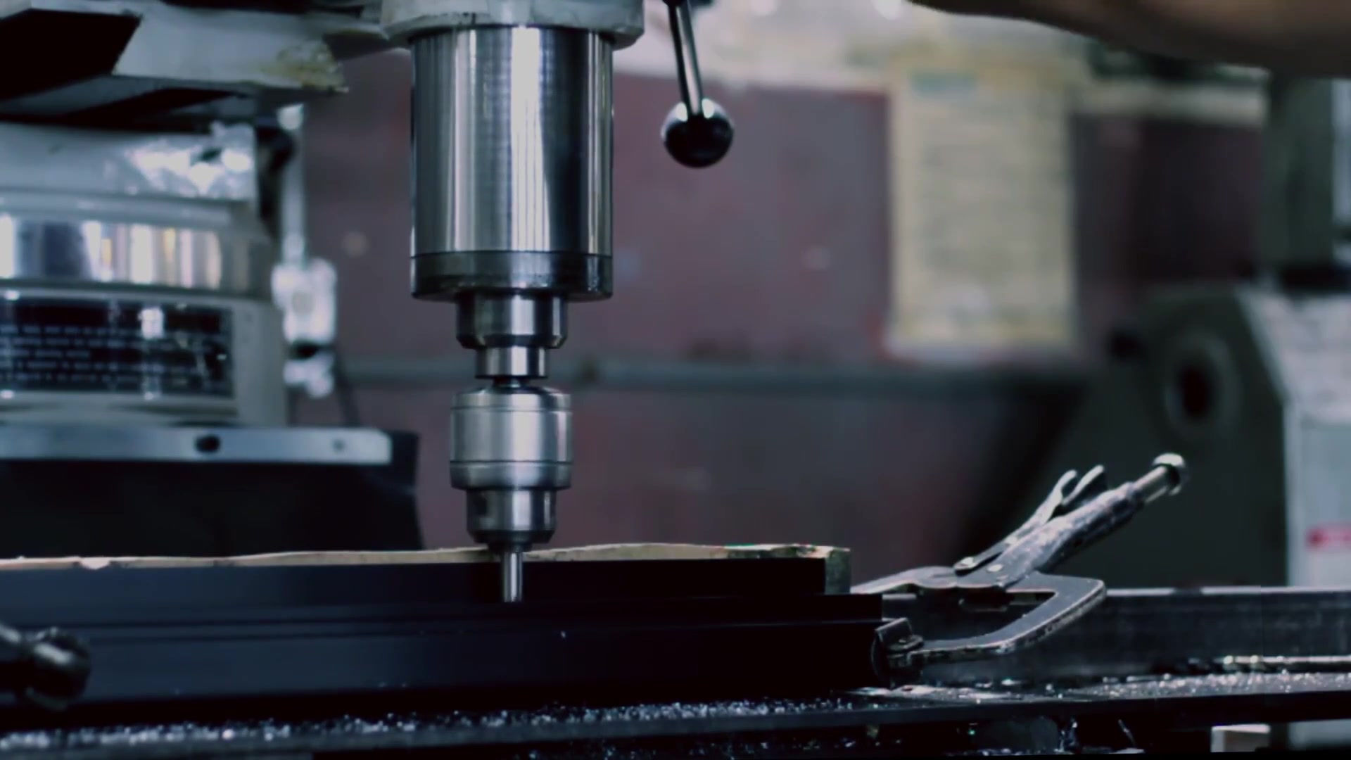
Manufaktur Custom Parts, Komponen, Rakitan, Produk Rampung, Mesin lan Peralatan Industri
Manufaktur Kontrak Domestik & Global
Outsourcing Produksi
Domestik, Pengadaan Global Produk Industri
Labeling pribadi / Label Putih Produk sampeyan nganggo Jeneng merek sampeyan
Product Finding & Locating Services
Desain Global lan Kemitraan Saluran
Integrasi Teknik
Layanan Teknik
Konsolidasi Global, Gudang, Logistik


Search Results
Search this site
164 results found with an empty search
- Plastic Rubber Metal Extrusions, Extrusion Dies, Aluminum Extruding
Plastic Rubber Metal Extrusions, Extrusion Dies, Aluminum Extruding, Pipe Tube Forming, Plastic Profiles, Metal Profiles Manufacturing, PVC at AGS-TECH Inc. Ekstrusi, Produk Ekstrusi, Ekstrusi We use the EXTRUSION process to manufacture products with a fixed cross sectional profile such as tubes, pipes and heat sinks. Even though many materials can be extruded, our most common extrusions are made of metal, polymers / plastic, ceramic obtained by either cold, warm or hot extrusion method. We call the extruded parts extrudate or extrudates if plural. Some specialized versions of the process we also perform are overjacketing, coextrusion and compound extrusion. We recommend that you click here to DOWNLOAD our Schematic Illustrations of Metal Ceramic and Plastic Extrusion Processes by AGS-TECH Inc. This will help you better understand the information we are providing you below. In extrusion material to be extruded is pushed or drawn through a die that has the desired cross-sectional profile. The process can be used to manufacture complex cross-sections with excellent surface finish and to work on brittle material. One can produce any length of parts using this process. To simplify the process steps: 1.) In warm or hot extrusions the material is heated and loaded into a container in the press. The material is pressed and pushed out of the die. 2.) Produced extrudate is is stretched for straightening, heat treated or cold worked for enhancing its properties. On the other hand COLD EXTRUSION takes place at around room temperature and has the advantages of less oxidation, high strength, closer tolerances, good surface finish and fastness. WARM EXTRUSION is performed above room temperature but below recrystallization point. It offers a compromise and balance for required forces, ductility and material properties and is therefore the choice for some applications. HOT EXTRUSION takes place above the material’s recrystallization temperature. This way it is easier to push the material through the die. However the equipment cost is high. The more complex an extruded profile, the more costly is the die (tooling) and the lower is the rate of production. The die cross sections as well as thicknesses have limitations that depend on the material to be extruded. Sharp corners in extrusion dies are always undesirable and to be avoided unless necessary. According to the material that is being extruded, we offer: • METAL EXTRUSIONS : Most common ones we produce are aluminum, brass, zinc, copper, steel, titanium, magnesium • PLASTIC EXTRUSION : Plastic is melted and formed into a continuous profile. Our common materials processed are polyethylene, nylon, polystyrene, polyvinyl chloride, polypropylene, ABS plastic, polycarbonate, acrylic. Typical products we manufacture include pipes and tubing, plastic frames. In the process small plastic beads / resin is gravity fed from hopper into barrel of the extrusion machine. Frequently we also mix colorants or other additives into hopper to give the product the required specifications and properties. The material entering the heated barrel is forced by the rotating screw to leave the barrel at the end and move through the screen pack for removal of contaminants in the molten plastic. After passing the screen pack the plastic enters the extrusion die. The die gives the moving soft plastic its profile shape as it passes through. Now the extrudate goes through a water bath for cooling. Other techniques AGS-TECH Inc. has been using for many years are: • PIPE & TUBING EXTRUSION : Plastic pipes and tubes are formed when plastics is extruded through a round shaping die and cooled in a water bath, then cut to length or coiled / spooled. Clear or colored, striped, single or dual wall, flexible or rigid, PE, PP, polyurethane, PVC, nylon, PC, silicone, vinyl or else, we have it all. We have stocked tubes as well as the capability to produce according to your specifications. AGS-TECH manufactures tubing to FDA, UL, and LE requirements for medical, electric & electronic, industrial and other applications. • OVERJACKETING / OVER JACKETING EXTRUSION : This technique applies an outer layer of plastic onto existing wire or cable. Our insulation wires are manufactured with this method. • COEXTRUSION : Multiple layers of material are simultaneously extruded. The multiple layers are delivered by multiple extruders. The various layer thicknesses can be adjusted to meet customer specifications. This process makes it possible to use multiple polymers each having a different functionality in the product. As a result, one can optimize a range of properties. • COMPOUND EXTRUSION: A single or multiple polymers are mixed with additives to obtain a plastic compound. Our twin-screw extruders produce compounding extrusions. Extrusion dies are generally inexpensive compared to metal moulds. If you are paying much more than a few thousand dollars for a small or medium size extrusion die extruding aluminum, you are probably paying too much. We are experts in determining which technique is the most cost effective, fastest and most suitable for your application. Sometimes extruding and then machining a part can save you a lot of cash. Before making a firm decision, ask us our opinion first. We have helped many customers make the right decisions. For some widely used metal extrusions, you can download our brochures and catalogs by clicking on the colored text below. If it is an off-shelf product meeting your requirements, it will be more economical. Download our medical tube and pipe extrusion capabilities Download our extruded heat sinks • SECONDARY MANUFACTURING & FABRICATION PROCESSES FOR EXTRUSIONS : Among value added processes we offer for extruded products are: -Custom tube & pipe bending, forming and shaping, tube cutoff, tube end forming, tube coiling, machining and finishing, hole drilling & piercing & punching, -Custom pipe and tube assemblies, tubular assembly, welding, brazing and soldering -Custom extrusion bending, forming and shaping -Cleaning, degreasing, pickling, passivation, polishing, anodizing, plating, painting, heat treating, annealing and hardening, marking, engraving and labeling, custom packaging. KLIK Product Finder-Locator Service PAGE sadurunge
- Fiber Optic Components, Splicing Enclosures, FTTH Node, CATV Products
Fiber Optic Components - Splicing Enclosures - FTTH Node - Fiber Distribution Box - Optical Platform - CATV Products - Telecommunication Optics - AGS-TECH Inc. Produk Fiber Optik We supply: • Fiber optic connectors, adapters, terminators, pigtails, patchcords, connector faceplates, shelves, communication racks, fiber distribution box, splicing enclosure, FTTH node, optical platform, fiber optic taps, splitters-combiners, fixed and variable optical attenuators, optical switch, DWDM, MUX/DEMUX, EDFA, Raman amplifiers and other amplifiers, isolator, circulator, gain flattener, custom fiberoptic assembly for telecommunication systems, optical waveguide devices, CATV products • Lasers and photodetectors, PSD (Position Sensitive Detectors), quadcells • Fiber optic assemblies for industrial applications (illumination, light delivery or inspection of pipe interiors, crevices, cavities, body interiors....). • Fiberoptic assemblies for medical applications (see our site http://www.agsmedical.com for medical endoscopes and couplers). Among the products our engineers have developed is a super slim 0.6 mm diameter flexible video endoscope, and a fiber end inspection interferometer. The interferometer was developed by our engineers for in-process and final inspection in manufacturing of fiber connectors. We use special bonding and attachment techniques and materials for rigid, reliable and long life assemblies. Even under extensive environmental cycling such as high temperature/low temperature; high humidity/low humidity our assemblies remain intact and keep working. Download our catalog for passive fiber optic components Download our catalog for active fiber optic products Download our catalog for free space optical components and assemblies Private Label Medical Endoscopes and Visualization Systems (We can put your company name and logo on these) KLIK Product Finder-Locator Service PREVIOUS PAGE
- Pneumatic and Hydraulic Actuators - Accumulators - AGS-TECH Inc. - NM
Pneumatic and Hydraulic Actuators - Accumulators - AGS-TECH Inc. - NM Aktuator Akumulator AGS-TECH is a leading manufacturer and supplier of PNEUMATIC and HYDRAULIC ACTUATORS for assembly, packaging, robotics, and industrial automation. Our actuators are known for performance, flexibility, and extremely long life, and welcome the challenge of many different types of operating environments. We also supply HYDRAULIC ACCUMULATORS which are devices in which potential energy is stored in the form of a compressed gas or spring, or by a raised weight to be used to exert a force against a relatively incompressible fluid. Our fast delivery of pneumatic and hydraulic actuators and accumulators will reduce your inventory costs and keep your production schedule on track. ACTUATORS: An actuator is a type of motor responsible for moving or controlling a mechanism or system. Actuators are operated by a source of energy. Hydraulic actuators are operated by hydraulic fluid pressure, and pneumatic actuators are operated by pneumatic pressure, and convert that energy into motion. Actuators are mechanisms by which a control system acts upon an environment. The control system may be a fixed mechanical or electronic system, a software-based system, a person, or any other input. Hydraulic actuators consist of cylinder or fluid motor that uses hydraulic power to facilitate mechanical operation. The mechanical motion may give an output in terms of linear, rotary or oscillatory motion. Since liquids are nearly impossible to compress, hydraulic actuators can exert considerable forces. Hydraulic actuators may have however limited acceleration. The actuator’s hydraulic cylinder consists of a hollow cylindrical tube along which a piston can slide. In single acting hydraulic actuators the fluid pressure is applied to just one side of the piston. The piston can move in only one direction, and a spring is generally used to give the piston a return stroke. Double acting actuators are used when pressure is applied on each side of the piston; any difference in pressure between the two sides of the piston moves the piston to one side or the other. Pneumatic actuators convert energy formed by vacuum or compressed air at high pressure into either linear or rotary motion. Pneumatic actuators enable large forces to be produced from relatively small pressure changes. These forces are often used with valves to move diaphragms to affect the flow of liquid through the valve. Pneumatic energy is desirable because it can respond quickly in starting and stopping as the power source does not need to be stored in reserve for operation. Industrial applications of actuators include automation, logic and sequence control, holding fixtures, and high-power motion control. Automotive applications of actuators on the other hand include power steering, power brakes, hydraulic brakes, and ventilation controls. Aerospace applications of actuators include flight-control systems, steering-control systems, air conditioning, and brake-control systems. COMPARING PNEUMATIC and HYDRAULIC ACTUATORS: Pneumatic linear actuators consist of a piston inside a hollow cylinder. Pressure from an external compressor or manual pump moves the piston inside the cylinder. As pressure is increased, the actuator’s cylinder moves along the axis of the piston, creating a linear force. The piston returns to its original position by either a spring-back force or fluid being supplied to the other side of the piston. Hydraulic linear actuators function similar to pneumatic actuators, but an incompressible liquid from a pump rather than pressurized air moves the cylinder. The benefits of pneumatic actuators come from their simplicity. The majority of pneumatic aluminum actuators have a maximum pressure rating of 150 psi with bore sizes ranging from 1/2 to 8 in., which can be converted into approximately 30 to 7,500 lb. of force. Steel pneumatic actuators on the other hand have a maximum pressure rating of 250 psi with bore sizes ranging from 1/2 to 14 in., and generate forces ranging from 50 to 38,465 lb. Pneumatic actuators generate precise linear motion by providing accuracies such as 0.1 inches and repeatabilities within .001 inches. Typical applications of pneumatic actuators are areas of extreme temperatures such as -40 F to 250 F. Using air, pneumatic actuators avoid using hazardous materials. Pneumatic actuators meet explosion protection and machine safety requirements because they create no magnetic interference due to their lack of motors. The cost of pneumatic actuators is low compared to hydraulic actuators. Pneumatic actuators are also lightweight, require minimal maintenance, and have durable components. On the other hand there are disadvantages of pneumatic actuators: Pressure losses and air’s compressibility make pneumatics less efficient than other linear-motion methods. Operations at lower pressures will have lower forces and slower speeds. A compressor must run continuously and apply pressure even if nothing is moving. To be efficient, pneumatic actuators must be sized for a specific job and cannot be used for other applications. Accurate control and efficiency requires proportional regulators and valves, which is costly and complex. Even though the air is easily available, it can be contaminated by oil or lubrication, leading to downtime and maintenance. Compressed air is a consumable that needs to be purchased. Hydraulic actuators on the other hand are rugged and suited for high-force applications. They can produce forces 25 times greater than pneumatic actuators of equal size and operate with pressures of up to 4,000 psi. Hydraulic motors have high horsepower-to-weight ratios by 1 to 2 hp/lb greater than a pneumatic motor. Hydraulic actuators can hold force and torque constant without the pump supplying more fluid or pressure, because fluids are incompressible. Hydraulic actuators can have their pumps and motors located a considerable distance away with still minimal power losses. However hydraulics will leak fluid and result in less efficiency. Hydraulic fluid leaks lead to cleanliness problems and potential damage to surrounding components and areas. Hydraulic actuators require many companion parts, such as fluid reservoirs, motors, pumps, release valves, and heat exchangers, noise-reduction equipment. As a result hydraulic linear motion systems are large and difficult to accommodate. ACCUMULATORS: These are used in fluid power systems to accumulate energy and to smooth out pulsations. Hydraulic system that utilize accumulators can use smaller fluid pumps because accumulators store energy from the pump during low demand periods. This energy is available for instantaneous use, released upon demand at a rate many times greater than could be supplied by the pump alone. Accumulators can also act as surge or pulsation absorbers by cushioning hydraulic hammers, reducing shocks caused by rapid operation or sudden starting and stopping of power cylinders in a hydraulic circuit. There are four major types of accumulators: 1.) The weight loaded piston type accumulators, 2.) Diaphragm type accumulators, 3.) Spring type accumulators and the 4.) Hydropneumatic piston type accumulators. The weight loaded type is much larger and heavier for its capacity than modern piston and bladder types. Both the weight loaded type, and mechanical spring type are very seldom used today. The hydro-pneumatic type accumulators use a gas as a spring cushion in conjunction with a hydraulic fluid, the gas and fluid being separated by a thin diaphragm or a piston. Accumulators have the following functions: -Energy Storage -Absorbing Pulsations -Cushioning Operating Shocks -Supplementing Pump Delivery -Maintaining Pressure -Acting as Dispensers Hydro-pneumatic accumulators incorporate a gas in conjunction with a hydraulic fluid. The fluid has little dynamic power storage capability. However, the relative incompressibility of a hydraulic fluid makes it ideal for fluid power systems and provides quick response to power demand. The gas, on the other hand, a partner to the hydraulic fluid in the accumulator, can be compressed to high pressures and low volumes. Potential energy is stored in the compressed gas to be released when needed. In the piston type accumulators the energy in the compressed gas exerts pressure against the piston separating the gas and the hydraulic fluid. The piston in turn forces the fluid from the cylinder into the system and to the location where useful work needs to be accomplished. In most fluid power applications, pumps are used to generate the required power to be used or stored in a hydraulic system, and pumps deliver this power in a pulsating flow. The piston pump, as commonly used for higher pressures produces pulsations detrimental to a high pressure system. An accumulator properly located in the system will substantially cushion these pressure variations. In many fluid power applications the driven member of the hydraulic system stops suddenly, creating a pressure wave which is sent back through the system. This shock wave can develop peak pressures several times greater than normal working pressures and can be the source of system failure or disturbing noise. The gas cushioning effect in an accumulator will minimize these shock waves. An example of this application is the absorption of shock caused by suddenly stopping the loading bucket on a hydraulic front end loader. An accumulator, capable of storing power, can supplement the fluid pump in delivering power to the system. The pump stores potential energy in the accumulator during idle periods of the work cycle, and the accumulator transfers this reserve power back to the system when the cycle requires emergency or peak power. This enables a system to utilize smaller pumps, resulting in cost and power savings. Pressure changes are observed in hydraulic systems when the liquid is subjected to rising or falling temperatures. Also, there may be pressure drops due to leakage of hydraulic fluids. Accumulators compensate for such pressure changes by delivering or receiving a small amount of hydraulic liquid. In the event the main power source should fail or be stopped, accumulators would act as auxiliary power sources, maintaining pressure in the system. Lastly, accumulators mcan be used to dispense fluids under pressure, such as lubricating oils. Please click on highlighted text below to download our product brochures for actuators and accumulators: - Pneumatic Cylinders - YC Series Hydraulic Cyclinder - Accumulators from AGS-TECH Inc KLIK Product Finder-Locator Service PAGE sadurunge
- General Sales Terms for Manufactured Parts & Products at AGS-TECH Inc.
General Sales Terms for Manufactured Parts & Products at AGS-TECH Inc.- a Flexible Global Custom Manufacturer, Fabricator, Consolidator, Engineering Integrator. Ketentuan Penjualan Umum ing AGS-TECH Inc Below you will find the GENERAL SALES TERMS AND CONDITIONS of AGS-TECH Inc. Seller AGS-TECH Inc. does submit a copy of these terms and conditions along with offers and quotes to its customers. These are general sales terms and conditions of seller AGS-TECH Inc. and should not be considered to be valid for every transaction. However please note that for any deviations or modifications to these general sales terms and conditions, buyers need to contact AGS-TECH Inc and obtain approval in writing. If no mutually agreed modified version of sales terms and conditions exist, these terms and conditions of AGS-TECH Inc. stated below shall apply. We also want to emphasize that the primary goal of AGS-TECH Inc. is to provide products and services that meet or exceed customers expectations, and make its customers globally competitive. Therefore the relationship of AGS-TECH Inc. will always be more of a long term sincere relationship and partnership with its customers and not one that is based on pure formality. 1. ACCEPTANCE. This proposal does not constitute an offer, but is an invitation to the Buyer to place an order which invitation shall be open for thirty (30) days. All orders are made subject to final written acceptance by AGS-TECH, INC. (hereinafter referred to as “seller”) The terms and conditions herein shall apply to and govern buyer’s order, and, in case of any inconsistency between these terms and conditions and buyer’s order, the terms and conditions herein shall prevail. Seller objects to the inclusion of any different or additional terms proposed by the buyer in its offer and if they are included in buyer’s acceptance, a contract for sale will result upon seller’s terms and conditions stated herein. 2. DELIVERY. The quoted delivery date is our best estimate based upon present scheduling requirements and may be deviated from without liability by a reasonably longer period at Seller’s discretion due to manufacturing contingencies. Seller shall not be liable for failure to deliver on any specific date or dates within any specific period of time in the event of hardships or causes beyond its control including, but not limited to, acts of God or the public enemy, governmental orders, restrictions or priorities, fires, floods, strikes, or other work stoppages, accidents, catastrophes, war conditions, riot or civil commotion, labor, material and/or transportation shortages, legal interferences or prohibitions, embargoes, defaults or delays of subcontractors and suppliers, or similar or different causes which render performance or timely delivery difficult or impossible; and, in any such event Seller shall not incur or be subject to any liability whatsoever. Buyer shall not by reason of any such cause, have any right of cancellation, nor any right to suspend, delay or otherwise prevent Seller from manufacturing, shipping or storing for Buyer’s account any material or other goods purchased hereunder, nor to withhold payment therefore. Buyer’s acceptance of delivery shall constitute a waiver of any claim for delay. If goods ready for shipment on or after the scheduled delivery date cannot be shipped because of Buyer’s request or for any other reason beyond Seller’s control, payment shall be made within thirty (30) days after Buyer has been notified that the same are ready for shipment, unless otherwise agreed in writing between Buyer and Seller. If at any time shipment is deferred or delayed, Buyer shall store the same at Buyer’s risk and expense and, if Buyer fails or refuses to store the same, Seller shall have the right to do so at Buyer’s risk and expense. 3. FREIGHT/RISK OF LOSS. Unless otherwise indicated, all shipments are made FOB, place of shipment and Buyer agrees to pay all charges for transportation, including insurance. Buyer assumes all risk of loss and damage from the time the goods are deposited with the carrier 4. INSPECTION/REJECTION. Buyer shall have ten (10) days after receipt of goods to inspect and either accept or reject. If goods are rejected, written notice of rejection and the specific reasons therefore must be sent to seller within such ten (10) day period after receipt. Failure to reject goods or to notify Seller of errors, shortages, or other non-compliance with the agreement within such ten (10) day period shall constitute irrevocable acceptance of goods and admission that they fully comply with the Agreement. 5. NON-RECURRING EXPENSE (NRE), DEFINITION/PAYMENT. Whenever used in the Seller’s quotation, acknowledgement or other communication, NRE is defined as a one-time Buyer borne cost for (a) the modification or adaptation of Seller owned tooling to allow manufacturing to Buyer’s exact requirements, or (b) the analysis and precise definition of the Buyer’s requirements. Buyer shall further pay for any necessary repairs or replacements to tools after tool life specified by Seller. At such time that Non-Recurring Expenses are specified by the Seller, Buyer shall pay 50% thereof with its Purchase Order and the balance thereof upon Buyer’s approval of the design, prototype or samples produced. 6. PRICES AND TAXES. Orders are accepted on the basis of prices listed. Any added expense incurred by the Seller because of delays in receipt of details, specifications, or other pertinent information, or because of changes requested by the Buyer shall be chargeable to the Buyer and payable upon invoice. The Buyer in addition to the purchase price shall assume and pay any and all sales, use, excise, license, property and/or other taxes and fees together with any interest and penalties thereon and expenses in connection therewith growing out of, relating to, affecting or pertaining to, the sale of property, service other subject matter of this order, and Buyer shall indemnify Seller and save and hold Seller harmless from and against any claim, demand or liability for and such tax or taxes, interest or 7. PAYMENT TERMS. Items ordered will be billed as shipments made and payment to Seller shall be net cash in United States funds, thirty (30) days from date of shipment by the Seller, unless otherwise specified in writing. No cash discount will be allowed. If Buyer delays manufacture or shipment, payment of the percentage of completion (based on the contract price) shall become immediately due. 8. LATE CHARGE. If invoices are not paid when due, Buyer agrees to pay late charges on the unpaid delinquent balance at the rate of 1 ½% thereof per month. 9. COST OF COLLECTION. Buyer agrees to pay any and all costs including but not limited to all attorney's fees, in the event Seller must refer Buyer’s account to an attorney for collection or enforcement of any of the terms and conditions of sale. 10. SECURITY INTEREST. Until payment is received in full, Seller shall retain a security interest in the goods hereunder and the Buyer authorizes Seller to execute on Buyer’s behalf a standard financing statement setting forth Seller’s security interest to be filed under the applicable filing provisions or any other document necessary to perfect Seller’s security interest in the goods in any state, country or jurisdiction. Upon Seller’s request, Buyer shall promptly execute any such documentation. 11. WARRANTY. Seller warrants that the component goods sold will meet the specifications set forth in writing by Seller. If Buyer’s order is for a complete optical system, from image to object, and Buyer provides all information to its requirements and use, Seller also warrants performance of the system, within the characteristics set forth in writing by Seller. Seller makes no warranty of fitness or merchantability and no warranty oral or written, express or implied, except as specifically set forth herein. The provisions and specifications attached hereto are descriptive only and are not to be understood as warranties. Seller’s warranty shall not apply if persons other than the seller have without written consent of seller performed any work or made any alteration in the goods supplied by the seller. Seller shall under no circumstances be liable for any loss of profits or other economic loss, or any special, indirect consequential damages arising from the loss of production or other damages or losses owing to the failure of seller’s goods or the supply by the seller of defective goods, or by reason of any other breach of this contract by seller. Buyer hereby waives any right to damages in the events it rescinds this contract for breach of warranty. This warranty extends only to the original buyer. No subsequent buyer or user is covered. 12. INDEMNIFICATION. Buyer agrees to indemnify Seller and save it harmless from and against any claim, demand or liability arising out of or in connection with the sale of the goods by Seller or the use of the goods by Buyer and this includes but is not limited to damage to property or persons. Buyer agrees to defend at its expense any suit against Seller respecting infringement (including contributory infringement) of any United States or other patent covering all or parts of the goods furnished under an order, its manufacture and/or its use and will pay costs, fees and/or damages awarded against Seller for such infringement by any final court decision; provided Seller notifies Buyer promptly of any charge of or suit for such infringement and tenders Buyer the defense of such suit; Seller having the right to be represented in such defense at Seller’s expense. 13. PROPRIETARY DATA. All specifications and technical material submitted by Seller and all inventions and discoveries made by Seller in carrying out any transaction based thereon are the property of Seller and are confidential and shall not be disclosed to or discussed with others. All such specifications and technical material submitted with this order or in carrying out any transaction based hereon shall be returned to Seller on demand. Descriptive matter furnished with this order is not binding as to detail unless certified correct by Seller in acknowledging an order relating thereto. 14. AGREEMENT MODIFICATIONS. The terms and conditions contained herein and any other terms and conditions stated in Seller’s proposal or specifications attached hereto, if any, shall constitute the complete agreement between Seller and Buyer and shall supersede all prior oral or written statements or understandings of any kind whatsoever made by the parties or their representatives. No statement subsequent to the acceptance of this order purporting to modify the said terms and conditions shall be binding unless consented to in writing by a duly authorized officer or manager of Seller. 15. CANCELLATION AND BREACH. This order shall not be countermanded, cancelled or altered by the Buyer, nor shall the Buyer otherwise cause the work or shipment to be delayed, except with the written consent and upon the terms and conditions approved by the Seller in writing. Such consent will be granted if at all, only upon the condition that Buyer shall pay Seller reasonable cancellation charges, which shall include compensation for the costs incurred, overhead, and lost profits. In event that the Buyer cancels this contract without Seller’s written consent or breaches this contract by failing to adhere to Seller for breach of contract and shall pay Sellers damages resulting from such breach including, but not limited to, lost profits, direct and indirect damages, costs incurred and attorneys’ fees. If Buyer is in default under this or any other contract with the Seller, or if Seller at any time shall not be satisfied with Buyer’s financial responsibility, Seller shall have the right, without prejudice to any other legal remedy, to suspend deliveries hereunder until such default or condition is remedied. 16. PLACE OF CONTRACT. Any contract arising out of the placing of any orders and the acceptance thereof by Seller, shall be a New Mexico contract and shall be interpreted and administered for all purposes under the laws of State of New Mexico. The Bernalillo County, NM is hereby designated as the place of trial for any action or proceeding arising out of or in connection with this Agreement. 17. LIMITATION OF ACTION. Any action by the Buyer against the Seller for the breach of this contract or the warranty described herein will be barred unless commenced within one year after the date of delivery or invoice, whichever is earlier. PAGE sadurunge
- Custom Manufactured Parts, Assemblies, Plastic Mold, Casting,Machining
Custom Manufactured Parts, Assemblies, Plastic Mold, Rubber Molding, Metal Casting, CNC Machining, Turning, Milling, Electrical Electronic Optical Assembly PCBA Parts & Majelis & Produk Custom Manufaktur Waca liyane Plastik & Karet Molds lan Molding Waca liyane Casting lan Machining Waca liyane Ekstrusi, Produk Ekstrusi Waca liyane Stampings & Sheet Metal Fabrikasi Waca liyane Metal Forging & Powder Metalurgi Waca liyane Kawat & Spring Forming Waca liyane Kaca & Keramik Forming & Shaping Waca liyane Aditif lan Rapid Manufaktur Waca liyane Pabrikan Bahan Komposit & Komposit Read More Proses Gabung & Majelis & Fastening We produce parts and assemblies for you and offer the following manufacturing processes: • Plastic and rubber moulds and moulded parts. Injection moulding, thermoforming, thermoset moulding, vacuum forming, blow moulding, rotational moulding, pour moulding, insert moulding and others. • Plastic, rubber and metal extrusions • Ferrous and nonferrous castings and machined parts produced by milling and turning techniques, Swiss-type machining. • Powder metallurgy parts • Metal and nonmetal stampings, sheet metal forming, welded sheet metal assemblies • Cold and hot forging • Wires, welded wire assemblies, wire forming • Various types of springs, spring forming • Gear manufacturing, gearbox, coupling, worm, speed reducer, cylinder, transmission belts, transmission chains, transmission components • Custom tempered and bulletproof glass compliant with NATO and military standards • Balls, bearings, pulleys and pulley assemblies • Valves and pneumatic components such as O-ring, washer and seals • Glass and ceramic parts and assemblies, vacuum proof and hermetic components, metal-ceramic and ceramic-ceramic bonding. • Various types of mechanical, optomechanical, electromechanical, optoelectronic assemblies. • Metal-rubber, metal-plastic bonding • Pipe and tube, pipe forming, bending and custom pipe assemblies, bellow manufacturing. • Fiberglass manufacturing • Welding using various techniques such as spot welding, laser welding, MIG, TIG. Ultrasonic welding for plastic parts. • Vast variety of surface treatments and surface finishes such as surface conditioning to enhance adhesion, depositing thin oxide layer to enhance adhesion of coating, sand blasting, chem-film, anodizing, nitriding, powder coating, spray coating, various advanced metallization and coating techniques including sputtering, electron beam, evaporation, plating, hard coatings such as diamond like carbon (DLC) or titanium for cutting and drilling tools. • Marking and labeling, laser marking on metal parts, printing on plastic and rubber parts Download brochure for Common Mechanical Engineering Terms used by Designers and Engineers We build products according to your particular specifications and requirements. In order to offer you the best quality, delivery and prices, we manufacture products globally in China, India, Taiwan, Philippines, South Korea, Malaysia, Sri Lanka, Turkey, USA, Canada, Germany, UK and Japan. This makes us much stronger and globally more competitive than any other custom manufacturer. Our products are manufactured in ISO9001:2000, QS9000, ISO14001, TS16949 certified environments and possess CE, UL mark and meet other industry standards. Once we are appointed for your project, we can take care of the entire manufacturing, assembly, testing, qualification, shipping & customs as you wish. If you prefer, we can warehouse your parts, assemble custom kits, print and label your company name & brand and drop ship to your customers. In other words, we can be your warehousing and distribution center as well if preferred. Since our warehouses are located near major seaports, it gives us logistical advantage. For example, when your products arrive at a major USA seaport, we can transport it directly to a nearby warehouse where we can store, assemble, make kits, relabel, print, package according to your choice and drop ship to your customers. We not only supply products. Our company works on custom contracts where we come to your site, evaluate your project on site and develop a project proposal custom designed for you. We then send our experienced team to implement the project. More information about our engineering work can be found on http://www.ags-engineering.com -We take small projects as well as large projects at industrial scale. As a first step, we can connect you either by phone , teleconferencing or MSN messenger to our expert team members, so you can communicate directly to an expert, ask questions and discuss your project. Call us and if needed we will come and visit you. PAGE sadurunge
- Passive Optical Components, Splitter & Combiner, DWDM, Optical Switch
Passive Optical Components - Splitter - Combiner - DWDM - Optical Switch - MUX / DEMUX - Circulator - Waveguide - EDFA Komponen Optik Pasif Manufaktur & Majelis We supply PASSIVE OPTICAL COMPONENTS ASSEMBLY, including: • FIBER OPTICAL COMMUNICATION DEVICES: Fiberoptic taps, splitters-combiners, fixed and variable optical attenuators, optical switch, DWDM, MUX/DEMUX, EDFA, Raman amplifiers and other amplifiers, circulators, gain flatteners, custom fiber optic assemblies for telecommunication systems, optical waveguide devices, splicing enclosure, CATV products. • INDUSTRIAL FIBER OPTICAL ASSEMBLY: Fiber optic assemblies for industrial applications (illumination, light delivery or inspection of pipe interiors, fiberscopes, endoscopes....). • FREE SPACE PASSIVE OPTICAL COMPONENTS and ASSEMBLY: These are optical components made from special grade glasses and crystals with superior transmission and reflection and other outstanding characteristics. Lenses, prisms, beamsplitters, waveplates, polarizers, mirrors, filters......etc. are among this category. You can download our off-shelf passive free space optical components and assemblies from our catalog below or ask us for custom designing and manufacturing them specially for your application. Among the passive optical assemblies our engineers have developed are: - A test and cutting station for polarized attenuators. - Video endoscopes and fiberscopes for medical applications. We use special bonding and attachment techniques and materials for rigid, reliable and long life assemblies. Even under extensive environmental cycling tests such as high temperature/low temperature; high humidity/low humidity our assemblies remain intact and keep working. Passive optical components and assemblies have become commodities in recent years. There really is no need to pay big amounts for these components. Contact us to take advantage of our competitive prices for the highest quality available. All our passive optical components and assemblies are manufactured in ISO9001 and TS16949 certified plants and conform to relevant international standards such as Telcordia for communication optics and UL, CE for industrial optical assemblies. Passive Fiber Optic Components and Assembly Brochure Passive Free Space Optical Components and Assembly Brochure KLIK Product Finder-Locator Service PREVIOUS PAGE
- Mechanical Testing Instruments - Tension Tester - Torsion Test Machine
Mechanical Testing Instruments - Tension Tester - Torsion Test Machine - Bending Tester - Impact Test Device - Concrete Tester - Compression Testing Machine - H Instrumen Tes Mekanik Among the large number of MECHANICAL TEST INSTRUMENTS we focus our attention to the most essential and popular ones: IMPACT TESTERS, CONCRETE TESTERS / SCHMIDT HAMMER, TENSION TESTERS, COMPRESSION TESTING MACHINES, TORSION TEST EQUIPMENT, FATIGUE TEST MACHINE, THREE & FOUR POINT BENDING TESTERS, COEFFICIENT OF FRICTION TESTERS, HARDNESS & THICKNESS TESTERS, SURFACE ROUGHNESS TESTERS, VIBRATION METERS, TACHOMETERS, PRECISION ANALYTICAL BALANCE. We offer our customers quality brands such as ELCOMETER, SADT, SINOAGE for under list prices. Please choose from the downloadable catalogs below the brand name and model number of the equipment you need and tell us whether you want a brand new or refurbished / used equipment: AMETEK-LLOYD Instruments Materials Testing (Versatile Materials Testing Equipment, Universal Test Machines, Tensile Strength, Compressibility, Hardness, Elasticity, Peeling, Adhesion...etc.) ELCOMETER Inspection Equipment Catalog ( Physical Test Equipment , Concrete Inspection Equipment, Concrete Test Hammers, Fineness Of Grind/Dispersion , Density & Specific Gravity , Viscosity & Flow Measurement , Film Application & Test Charts , Drying Time & Permeability , Washability & Abrasion , Hardness & Scratch Resistance , Elasticity, Bend & Impact Testers , Flash Point ) HAIDA Adhesive Tape Peel Test Machine HAIDA Computerized Universal Test Machine with Extensometer HAIDA Computerized Universal Test Machine with Large Capacity (Double Column) HAIDA Computer Servo Tensile Test Machine HAIDA Desktop Tensile Test Machine HAIDA Double-Column Universal Testing Machine HAIDA Electro-Hydraulic Universal Testing Machine HAIDA Extra - Height Tensile Test Machine HAIDA Tensile Test Machines HAIDA Universal Testing Machine HAIDA Universal Test Machine HAIDA Universal Test Machine with Temperature Chamber INSTRON Compression and Tension Test Instruments SADT-SINOAGE Brand Metrology and Test Equipment, please CLICK HERE. Here you will find some of these testing equipment such as concrete testers and surface roughness tester. Let us examine these test devices in some detail: SCHMIDT HAMMER / CONCRETE TESTER : This test instrument, also sometimes called a SWISS HAMMER or a REBOUND HAMMER, is a device to measure the elastic properties or strength of concrete or rock, mainly surface hardness and penetration resistance. The hammer measures the rebound of a spring-loaded mass impacting against the surface of the sample. The test hammer will hit the concrete with a predetermined energy. The hammer’s rebound depends on the hardness of the concrete and is measured by the test equipment. Taking a conversion chart as a reference, the rebound value can be used to determine the compressive strength. The Schmidt hammer is an arbitrary scale ranging from 10 to 100. Schmidt hammers come with several different energy ranges. Their energy ranges are: (i) Type L-0.735 Nm impact energy, (ii) Type N-2.207 Nm impact energy; and (iii) Type M-29.43 Nm impact energy. Local variation in the sample. To minimize local variation in the samples it is recommended to take a selection of readings and take their average value. Prior to testing, the Schmidt hammer needs to be calibrated using a calibration test anvil supplied by the manufacturer. 12 readings should be taken, dropping the highest and lowest, and then taking the average of the ten remaining readings. This method is considered an indirect measurement of the strength of the material. It provides an indication based on surface properties for comparison between samples. This test method for testing concrete is governed by ASTM C805. On the other hand, the ASTM D5873 standard describes the procedure for testing of rock. Inside of our SADT brand catalog you will find the following products: DIGITAL CONCRETE TEST HAMMER SADT Models HT-225D/HT-75D/HT-20D - The SADT Model HT-225D is an integrated digital concrete test hammer combining data processor and test hammer into a single unit. It is widely used for non destructive quality testing of concrete and building materials. From its rebound value, the compressive strength of concrete can be calculated out automatically. All test data can be stored in memory and transferred to PC by USB cable or wirelessly by Bluetooth. The models HT-225D and HT-75D have measuring range of 10 – 70N/mm2, whereas the model HT-20D has only 1 – 25N/mm2. The impact energy of HT-225D is 0.225 Kgm and is suitable for testing ordinary building and bridge construction, the impact energy of HT-75D is 0.075 Kgm and is suitable for testing small and impact-sensitive parts of concrete and artificial brick, and finally the impact energy of HT-20D is 0.020Kgm and suitable for testing mortar or clay products. IMPACT TESTERS: In many manufacturing operations and during their service lives, many components need to be subjected to impact loading. In the impact test, the notched specimen is placed in an impact tester and broken with a swinging pendulum. There are two major types of this test: The CHARPY TEST and the IZOD TEST. For the Charpy test the specimen are supported at both ends, whereas for the Izod test they are supported only at one end like a cantilever beam. From the amount of swing of the pendulum, the energy dissipated in breaking the specimen is obtained, this energy is the impact toughness of the material. Using the impact tests, we can determine the ductile-brittle transition temperatures of materials. Materials with high impact resistance generally have high strength and ductility. These tests also reveal the sensitivity of a material’s impact toughness to surface defects, because the notch in the specimen can be considered a surface defect. TENSION TESTER : The strength-deformation characteristics of materials are determined using this test. Test specimen are prepared according to ASTM standards. Typically, solid and round specimens are tested, but flat sheets and tubular samples may also be tested using tension test. The original length of a specimen is the distance between gage marks on it and is typically 50 mm long. It is denoted as lo. Longer or shorter lengths can be used depending on the specimens and products. The original cross-sectional area is denoted as Ao. The engineering stress or also called nominal stress is then given as: Sigma = P / Ao And the engineering strain is given as: e = (l – lo) / lo In the linear elastic region, the specimen elongates proportionately to the load up to the proportional limit. Beyond this limit, even though not linearly, the specimen will continue to deform elastically up to the yield point Y. In this elastic region, the material will return to its original length if we remove the load. Hooke’s Law applies in this region and gives us the Young’s Modulus: E = Sigma / e If we increase the load and move beyond the yield point Y, the material begins to yield. In other words, the specimen begins to undergo plastic deformation. Plastic deformation means permanent deformation. The cross-sectional area of the specimen decreases permanently and uniformly. If specimen is unloaded at this point, the curve follows a straight line downward and parallel to the original line in the elastic region. If the load is further increased, the curve reaches a maximum and begins to decrease. The maximum stress point is called the tensile strength or ultimate tensile strength and is denoted as UTS. The UTS can be interpreted as the overall strength of materials. When load is greater than the UTS, necking occurs on the specimen and the elongation between gage marks is no longer uniform. In other words, the specimen becomes really thin at the location where necking occurs. During necking, the elastic stress drops. If the test is continued, the engineering stress drops further and the specimen fractures at the necking region. The stress level at fracture is the fracture stress. The strain at point of fracture is an indicator of ductility. The strain up to the UTS is referred to as uniform strain, and the elongation at fracture is referred to as total elongation. Elongation = ((lf – lo) / lo) x 100 Reduction of Area = ((Ao – Af) / Ao) x 100 Elongation and reduction of area are good indicators of ductility. COMPRESSION TESTING MACHINE ( COMPRESSION TESTER ) : In this test, the specimen is subjected to a compressive load contrary to the tensile test where the load is tensile. Generally, a solid cylindrical specimen is placed between two flat plates and compressed. Using lubricants at the contact surfaces, a phenomenon known as barreling is prevented. Engineering strain rate in compression is given by: de / dt = - v / ho, where v is die speed, ho original specimen height. True strain rate on the other hand is: de = dt = - v/ h, with h being the instantaneous specimen height. To keep the true strain rate constant during the test, a cam plastometer thru a cam action reduces the magnitude of v proportionally as the specimen height h decreases during the test. Using the compression test ductilities of materials are determined by observing cracks formed on barreled cylindrical surfaces. Another test with some differences in the die and workpiece geometries is the PLANE-STRAIN COMPRESSION TEST, which gives us the yield stress of the material in plane strain denoted widely as Y’. Yield stress of materials in plane strain can be estimated as: Y’ = 1.15 Y TORSION TEST MACHINES (TORSIONAL TESTERS) : The TORSION TEST is another widely used method for determining material properties. A tubular specimen with a reduced mid-section is used in this test. Shear stress, T is given by: T = T / 2 (Pi) (square of r) t Here, T is the applied torque, r is the mean radius and t is the thickness of the reduced section in the middle of the tube. Shear strain on the other hand is given by: ß = r Ø / l Here l is the length of the reduced section and Ø is the twist angle in radians. Within the elastic range, the shear modulus (modulus of rigidity) is expressed as: G = T / ß The relation between shear modulus and the modulus of elasticity is: G = E / 2( 1 + V ) The torsion test is applied to solid round bars at elevated temperatures to estimate the forgeability of metals. The more twists the material can withstand prior to failure, the more forgeable it is. THREE & FOUR POINT BENDING TESTERS : For brittle materials, the BEND TEST (also called FLEXURE TEST) is suitable. A rectangularly shaped specimen is supported at both ends and a load is applied vertically. The vertical force is applied at either one point as in the case of three point bending tester, or at two points as in the case of a four point test machine. The stress at fracture in bending is referred to as the modulus of rupture or transverse rupture strength. It is given as: Sigma = M c / I Here, M is the bending moment, c is one-half of the specimen depth and I is the moment of inertia of the cross-section. The magnitude of stress is the same in both three and four-point bending when all other parameters are kept constant. The four-point test is likely to result in a lower modulus of rupture as compared to the three-point test. Another superiority of the four-point bending test over the three point bending test is that its results are more consistent with less statistical scattering of values. FATIGUE TEST MACHINE: In FATIGUE TESTING, a specimen is subjected repeatedly to various states of stress. The stresses are generally a combination of tension, compression and torsion. The test process can be resembled to bending a piece of wire alternately in one direction, then the other until it fractures. The stress amplitude can be varied and is denoted as “S”. The number of cycles to cause total failure of the specimen is recorded and is denoted as “N”. Stress amplitude is the maximum stress value in tension and compression to which the specimen is subjected. One variation of the fatigue test is performed on a rotating shaft with a constant downward load. The endurance limit (fatigue limit) is defined as the max. stress value the material can withstand without fatigue failure regardless of the number of cycles. Fatigue strength of metals is related to their ultimate tensile strength UTS. COEFFICIENT OF FRICTION TESTER : This test equipment measures the ease with which two surfaces in contact are able to slide past one another. There are two different values associated with the coefficient of friction, namely the static and kinetic coefficient of friction. Static friction applies to the force necessary to initialize motion between the two surfaces and kinetic friction is the resistance to sliding once the surfaces are in relative motion. Appropriate measures need to be taken prior to testing and during testing to ensure freedom from dirt, grease and other contaminants that could adversely affect test results. ASTM D1894 is the main coefficient of friction test standard and is used by many industries with different applications and products. We are here to offer you the most suitable test equipment. If you need a custom set-up specifically designed for your application, we can modify existing equipment accordingly in order to meet your requirements and needs. HARDNESS TESTERS : Please go to our related page by clicking here THICKNESS TESTERS : Please go to our related page by clicking here SURFACE ROUGHNESS TESTERS : Please go to our related page by clicking here VIBRATION METERS : Please go to our related page by clicking here TACHOMETERS : Please go to our related page by clicking here For details and other similar equipment, please visit our equipment website: http://www.sourceindustrialsupply.com KLIK Product Finder-Locator Service PAGE sadurunge
- Thermal Infrared Test Equipment, Thermal Camera, Differential Scanning
Thermal Infrared Test Equipment, Thermal Camera, Differential Scanning Calorimeter, Thermo Gravimetric Analyzer, Thermo Mechanical Analyzer, Dynamic Mechanical Peralatan Tes Termal & IR KLIK Product Finder-Locator Service Among the many THERMAL ANALYSIS EQUIPMENT, we focus our attention to the popular ones in industry, namely the DIFFERENTIAL SCANNING CALORIMETRY ( DSC ), THERMO-GRAVIMETRIC ANALYSIS ( TGA ), THERMO-MECHANICAL ANALYSIS ( TMA ), DILATOMETRY,DYNAMIC MECHANICAL ANALYSIS ( DMA ), DIFFERENTIAL THERMAL ANALYSIS ( DTA). Our INFRARED TEST EQUIPMENT involves THERMAL IMAGING INSTRUMENTS, INFRARED THERMOGRAPHERS, INFRARED CAMERAS. Some applications for our thermal imaging instruments are Electrical and Mechanical System Inspection, Electronic Component Inspection, Corrosion Damage and Metal Thinning, Flaw Detection. Please download catalogs from colored links below and let us know your prefered brand and model number of the product. You can purchase brand new or refurbished / used Thermal & IR Test Equipment from us: FLUKE Test Tools Catalog (includes Thermal Imagers, Thermometers) HAIDA Color Assessment Cabinet Private Label Hand Tools for Every Industry (This catalog contains a few thermal & IR test instruments. We can private label these hand tools if you wish. In other words, we can put your company name, brand and label on them. This way you can promote your brand by reselling these to your customers.) DIFFERENTIAL SCANNING CALORIMETERS (DSC) : A technique in which the difference in the amount of heat required to increase the temperature of a sample and reference is measured as a function of temperature. Both the sample and reference are maintained at nearly the same temperature throughout the experiment. The temperature program for a DSC analysis is established so that the sample holder temperature increases linearly as a function of time. The reference sample has a well-defined heat capacity over the range of temperatures to be scanned. DSC experiments provide as a result a curve of heat flux versus temperature or versus time. Differential scanning calorimeters are frequently used to study what happens to polymers when they're heated. The thermal transitions of a polymer can be studied using this technique. Thermal transitions are changes that take place in a polymer when they are heated. The melting of a crystalline polymer is an example. The glass transition is also a thermal transition. DSC thermal analysis is carried out for determining Thermal Phase Changes, Thermal Glass Transition Temperature (Tg), Crystalline Melt Temperatures, Endothermic Effects, Exothermic Effects, Thermal Stabilities, Thermal Formulation Stabilities, Oxidative Stabilities, Transition Phenomena, Solid State Structures. DSC analysis determines the Tg Glass Transition Temperature, temperature at which amorphous polymers or an amorphous part of a crystalline polymer go from a hard brittle state to a soft rubbery state, melting point, temperature at which a crystalline polymer melts, Hm Energy Absorbed (joules/gram), amount of energy a sample absorbs when melting, Tc Crystallization Point, temperature at which a polymer crystallizes upon heating or cooling, Hc Energy Released (joules/gram), amount of energy a sample releases when crystallizing. Differential Scanning Calorimeters can be used to determine the thermal properties of plastics, adhesives, sealants, metal alloys, pharmaceutical materials, waxes, foods, oils and lubricants and catalysts….etc. DIFFERENTIAL THERMAL ANALYZERS (DTA): An alternative technique to DSC. In this technique it is the heat flow to the sample and reference that remains the same instead of the temperature. When the sample and reference are heated identically, phase changes and other thermal processes cause a difference in temperature between the sample and reference. DSC measures the energy required to keep both the reference and the sample at the same temperature whereas DTA measures the difference in temperature between the sample and the reference when they are both put under the same heat. So they are similar techniques. THERMOMECHANICAL ANALYZER (TMA) : The TMA reveals the change in the dimensions of a sample as a function of temperature. One can regard TMA as a very sensitive micrometer. The TMA is a device that allows precise measurements of position and can be calibrated against known standards. A temperature control system consisting of a furnace, heat sink and a thermocouple surrounds the samples. Quartz, invar or ceramic fixtures hold the samples during tests. TMA measurements record changes caused by changes in the free volume of a polymer. Changes in free volume are volumetric changes in the polymer caused by the absorption or release of heat associated with that change; the loss of stiffness; increased flow; or by the change in relaxation time. The free volume of a polymer is known to be related to viscoelasticity, aging, penetration by solvents, and impact properties. The glass transition temperature Tg in a polymer corresponds to the expansion of the free volume allowing greater chain mobility above this transition. Seen as an inflection or bending in the thermal expansion curve, this change in the TMA can be seen to cover a range of temperatures. The glass transition temperature Tg is calculated by an agreed upon method. Perfect agreement is not immediately witnessed in the value of the Tg when comparing different methods, however if we carefully examine the agreed upon methods in determining the Tg values then we understand that there is actually good agreement. Besides its absolute value, the width of the Tg is also an indicator of changes in the material. TMA is a relatively simple technique to carry out. TMA is often used for measuring Tg of materials such as highly cross-linked thermoset polymers for which the Differential Scanning Calorimeter (DSC) is difficult to use. In addition to Tg, the coefficient of thermal expansion (CTE) is obtained from thermomechanical analysis. The CTE is calculated from the linear sections of the TMA curves. Another useful result the TMA can provide us is finding out the orientation of crystals or fibers. Composite materials may have three distinct thermal expansion coefficients in the x, y and z directions. By recording the CTE in x, y and z directions one may understand in which direction fibers or crystals are predominantly oriented. To measure the bulk expansion of the material a technique called DILATOMETRY can be used. The sample is immersed in a fluid such as silicon oil or Al2O3 powder in the dilatometer, run thru the temperature cycle and the expansions in all directions are converted to a vertical movement, which is measured by the TMA. Modern thermomechanical analyzers make this easy for users. If a pure liquid is used, the dilatometer is filled with that liquid instead of the silicon oil or alumina oxide. Using diamond TMA the users can run stress strain curves, stress relaxation experiments, creep-recovery and dynamic mechanical temperature scans. The TMA is an indispensible test equipment for industry and research. THERMOGRAVIMETRIC ANALYZERS ( TGA ) : Thermogravimetric Analysis is a technique where the mass of a substance or specimen is monitored as a function of temperature or time. The sample specimen is subjected to a controlled temperature program in a controlled atmosphere. The TGA measures a sample’s weight as it is heated or cooled in its furnace. A TGA instrument consists of a sample pan that is supported by a precision balance. That pan resides in a furnace and is heated or cooled during the test. The mass of the sample is monitored during the test. Sample environment is purged with an inert or a reactive gas. Thermogravimetric analyzers can quantify loss of water, solvent, plasticizer, decarboxylation, pyrolysis, oxidation, decomposition, weight % filler material, and weight % ash. Depending on the case, information may be obtained upon heating or cooling. A typical TGA thermal curve is displayed from left to right. If the TGA thermal curve descends, it indicates a weight loss. Modern TGAs are capable of conducting isothermal experiments. Sometimes the user may want to use a reactive sample purge gases, such as oxygen. When using oxygen as a purge gas user may want to switch gases from nitrogen to oxygen during the experiment. This technique is frequently used to identify the percent carbon in a material. Thermogravimetric analyzer can be used to compare two similar products, as a quality control tool to ensure products meet their material specifications, to ensure products meet safety standards, to determine carbon content, identifying counterfeit products, to identify safe operating temperatures in various gases, to enhance product formulation processes, to reverse engineer a product. Finally it is worth mentioning that combinations of a TGA with a GC/MS are available. GC is short for Gas Chromatography and MS is short for Mass Spectrometry. DYNAMIC MECHANICAL ANALYZER ( DMA) : This is a technique where a small sinusoidal deformation is applied to a sample of known geometry in a cyclic manner. The materials response to stress, temperature, frequency and other values is then studied. The sample can be subjected to a controlled stress or a controlled strain. For a known stress, the sample will deform a certain amount, depending on its stiffness. DMA measures stiffness and damping, these are reported as modulus and tan delta. Because we are applying a sinusoidal force, we can express the modulus as an in-phase component (the storage modulus), and an out of phase component (the loss modulus). The storage modulus, either E’ or G’, is the measure of the sample’s elastic behavior. The ratio of the loss to the storage is the tan delta and is called damping. It is considered a measure of the energy dissipation of a material. Damping varies with the state of the material, its temperature, and with the frequency. DMA is sometimes called DMTA standing for DYNAMIC MECHANICAL THERMAL ANALYZER. Thermomechanical Analysis applies a constant static force to a material and records the material dimensional changes as temperature or time varies. The DMA on the other hand, applies an oscillatory force at a set frequency to the sample and reports changes in stiffness and damping. DMA data provides us modulus information whereas the TMA data gives us the coefficient of thermal expansion. Both techniques detect transitions, but DMA is much more sensitive. Modulus values change with temperature and transitions in materials can be seen as changes in the E’ or tan delta curves. This includes glass transition, melting and other transitions that occur in the glassy or rubbery plateau which are indicators of subtle changes in the material. THERMAL IMAGING INSTRUMENTS, INFRARED THERMOGRAPHERS, INFRARED CAMERAS : These are devices that form an image using infrared radiation. Standard everyday cameras form images using visible light in the 450–750 nanometer wavelength range. Infrared cameras however operate in the infrared wavelength range as long as 14,000 nm. Generally, the higher an object's temperature, the more infrared radiation is emitted as black-body radiation. Infrared cameras work even in total darkness. Images from most infrared cameras have a single color channel because the cameras generally use an image sensor that does not distinguish different wavelengths of infrared radiation. To differentiate wavelengths color image sensors require a complex construction. In some test instruments these monochromatic images are displayed in pseudo-color, where changes in color are used rather than changes in intensity to display changes in the signal. The brightest (warmest) parts of images are customarily colored white, intermediate temperatures are colored red and yellow, and the dimmest (coolest) parts are colored black. A scale is generally shown next to a false color image to relate colors to temperatures. Thermal cameras have resolutions considerably lower than that of optical cameras, with values in the neighborhood of 160 x 120 or 320 x 240 pixels. More expensive infrared cameras can achieve a resolution of 1280 x 1024 pixels. There are two main categories of thermographic cameras: COOLED INFRARED IMAGE DETECTOR SYSTEMS and UNCOOLED INFRARED IMAGE DETECTOR SYSTEMS. Cooled thermographic cameras have detectors contained in a vacuum-sealed case and are cryogenically cooled. The cooling is necessary for the operation of the semiconductor materials used. Without cooling, these sensors would be flooded by their own radiation. Cooled infrared cameras are however expensive. Cooling requires much energy and is time-consuming, requiring several minutes of cooling time prior to working. Although the cooling apparatus is bulky and expensive, cooled infrared cameras offer users superior image quality compared to uncooled cameras. The better sensitivity of cooled cameras allows the use of lenses with higher focal length. Bottled nitrogen gas can be used for cooling. Uncooled thermal cameras use sensors operating at ambient temperature, or sensors stabilized at a temperature close to ambient using temperature control elements. Uncooled infrared sensors are not cooled to low temperatures and therefore do not require bulky and expensive cryogenic coolers. Their resolution and image quality however is lower as compared to cooled detectors. Thermographic cameras offer many opportunities. Overheating spots is power lines can be located and repaired. Electric circuitry can be observed and unusually hot spots can indicate problems such as short circuit. These cameras are also widely used in buildings and energy systems to locate places where there is significant heat loss so that better heat insulation can be considered at those points. Thermal imaging instruments serve as non-destructive test equipment. For details and other similar equipment, please visit our equipment website: http://www.sourceindustrialsupply.com PAGE sadurunge
- Hydraulic Pipe Cutters - Vacuum Lifters - Vacuum Manipulators
Pneumatic Hydraulic & Vacuum Tools, Air Tool, Hydraulic Powered Tools, Air Screwdrivers, Air Drills, Pneumatic Nail Guns, Air Die Grinders,Hydraulic Pipe Cutter Piranti kanggo Hidrolik & Pneumatik & Vakum We also supply widely used industrial tools for pneumatic, hydraulic and vacuum systems. PNEUMATIC TOOLS (also called AIR TOOLS or AIR-POWERED TOOLS or PNEUMATIC-POWERED TOOLS are types of power tools driven by compressed air, supplied by air compressors. Pneumatic tools can also be driven by compressed carbon dioxide (CO2) stored in small cylinders allowing portability and use where no compressed air lines are available. Pneumatic tools are safer to run and easier to maintain than electric power tool equivalents. Pneumatic tools also have a higher power-to-weight ratio, allowing a smaller, lighter tool to accomplish the same task. General grade pneumatic tools with short life span are generally less expensive. Both disposable as well as industrial grade pneumatic tools with long life span are available. Generally speaking, pneumatic tools are cheaper than the equivalent electric-powered tools. Air tools are becoming more and more popular in the DIY (Do it yourself) market. HYDRAULIC-POWERED TOOLS on the other hand are generally more powerful tools used for applications that require higher pressures and forces. Liquids are much much less compressible than gases and that is the reason why hydraulic powered tools are able to supply such large forces. INDUSTRIAL VACUUM TOOLS offered are mostly manipulators, grippers, holders, lifters used in handling, moving, removing parts and components in industrial settings. Vacuum is also used in packaging to remove air from inside packages to extend the shelf life of products and protect them from moisture, air and early corrosion and decay. We supply both off-shelf and custom manufactured pneumatic, hydraulic and vacuum tools. Here is a list of some common tools: AIR SCREWDRIVERS, ROUTERS AIR RATCHET AIR & HYDRAULIC DRILLS PNEUMATIC NAIL GUN AIR & HYDRAULIC HAMMERS RIVETER & RIVETING HAMMER AIR GUNS and NOZZLES SANDBLASTER AIRBRUSH PAINT SPRAYER AIR CAULK GUNS AIR DIE GRINDERS AIR SANDER AIR BEVELERS AIR CUT-OFF TOOLS SWIVEL CONNECTORS AIR KNIVES PNEUMATIC SLIDES AIR CANNONS AIR AMPLIFIERS AIR CONVEYORS HYDRAULIC & PNEUMATIC TORQUE WRENCH HYDRAULIC PRESSES HYDRAULIC PIPE CUTTERS HYDRAULIC PULLER HYDRAULIC BOLTING TOOLS HYDRAULIC WORKHOLDING DEVICES VACUUM MANIPULATORS and GRIPPERS VACUUM LIFTERS VACUUM PACKAGING TOOLS CUSTOM SPECIALTY TOOLS Click links below to download our relevant brochures: - Air Tool Kits - Air Tools Accessories and Special Industrial Pneumatic Tools - Air Nailers and Staplers - Air Spray Guns - Air Brushes - Air Guns, Hoses, Connectors, Splitters and Accessories - DIY Air Tools - DIY Air Tools Assortment & Wet Air Tools - Oil-Less Mini Air Compressors - Private Label Pneumatic Air Blow Guns (We can put your company name, brand, logo, label on these if you wish) - Private Label Pneumatic Compressed Air Tools (We can put your company name, brand, logo, label on these if you wish) - Professional Air Tools Part-1 - Professional Air Tools Part-2 - Professional Air Tools Part-3 - Professional Air Tools Assortment KLIK Product Finder-Locator Service PAGE sadurunge
- Optical Displays, Screen, Monitors Manufacturing - AGS-TECH Inc.
Optical Displays, Screen, Monitors, Touch Panel Manufacturing Manufaktur & Perakitan Tampilan Optik, Layar, Monitor Unduh brosur kanggo PROGRAM KEMITRAAN DESIGN KLIK Product Finder-Locator Service PAGE sadurunge
- Machine Elements Manufacturing, Gears, Gear Drives, Bearings, Keys, Splines
Machine Elements Manufacturing, Gears, Gear Drives, Bearings, Keys, Splines, Pins, Shafts, Seals, Fasteners, Clutch, Cams, Followers, Belts, Couplings, Shafts Manufaktur Elemen Mesin Waca liyane Sabuk & Rantai & Majelis Penggerak Kabel Waca liyane Gears & Gear Drive Assembly Waca liyane Couplings & Bearings Manufacturing Waca liyane Keys & Splines & Pin Manufaktur Waca liyane Cams & Followers & Linkages & Manufaktur Roda Ratchet Waca liyane Produksi Shaft Waca liyane Produksi Seal Mekanik Waca liyane Kopling & Brake Assembly Waca liyane Fasteners Manufaktur Waca liyane Majelis Mesin Prasaja MACHINE ELEMENTS are elementary components of a machine. These elements consist of three basic types: 1.) Structural components including frame members, bearings, axles, splines, fasteners, seals, and lubricants. 2.) Mechanisms controlling movement in various ways such as gear trains, belt or chain drives, linkages, cam and follower systems, brakes & clutches. 3.) Control components like buttons, switches, indicators, sensors, actuators and computer controllers. Most of the machine elements we offer you are standardized to common sizes, but custom made machine elements are also available for your specialized applications. Customization of machine elements can take place on existing designs that are in our downloadable catalogs or on brand new designs. Prototyping and manufacturing of machine elements can be carried forward once a design is approved by both parties. If new machine elements need to be designed & manufactured, our customers either email us their own blueprints and we review them for approval, or they ask us to design machine elements for their application. In the latter case we use all input from our customers and design the machine elements and send the finalized blueprints to our clients for approval. Once approved, we produce first articles and subsequently manufacture the machine elements according to the final design. At any stage of this work, in case a particular machine element design performs unsatisfactorily in the field (which is rare), we review the entire project and make alterations jointly with our clients as needed. It is our standard practice to sign nondisclosure agreements (NDA) with our customers for the design of machine elements or any other product whenever needed or required. Once machine elements for a particular customer are custom designed and manufactured, we assign a product code to it and only produce and sell them to our customer who owns the product. We reproduce the machine elements using the developed tools, molds and procedures as many times as needed and whenever our customer reorders them. In other words, once a custom machine element is designed and produced for you, the intellectual property as well as all tooling and molds are reserved and stocked indefinitely by us for you and the products reproduced as you wish. We also offer our clients engineering services by creatively combining machine elements into a component or assembly that serves an application and meets or exceeds our customers expectations. Plants fabricating our machine elements are qualified by either ISO9001, QS9000 or TS16949. In addition, most of our products do have CE or UL mark and meet internationally relevant standards such as ISO, SAE, ASME, DIN. Please click on submenus to obtain detailed information about our machine elements including: - Belts, Chains and Cable Drives - Gears and Gear Drives - Couplings & Bearings - Keys & Splines & pins - Cams & Linkages - Shafts - Mechanical Seals - Industrial Clutch & Brake - Fasteners - Simple Machines We have prepared a reference brochure for our customers, designers and developers of new products including machine elements. You can familiar yourself with some commonly used terms in machine components design: Download brochure for Common Mechanical Engineering Terms used by Designers and Engineers Our machine elements find applications in a variety of fields such as industrial machinery, automation systems, test and metrology equipment, transportation equipment, construction machines and practically anywhere you can think of. AGS-TECH develops and manufactures machine elements from various materials depending on application. Materials used for machine elements could range from molded plastics used for toys to case hardened and specially coated steel for industrial machinery. Our designers use state of the art professional software and design tools for developing machine elements, taking into consideration details such as angles in gear teeth, stresses involved, wear rates….etc. Please scroll through our submenus and download our product brochures and catalogs to see if you can locate off-the-shelf machine elements for your application. If you cannot find a good match for your application, please let us know and we will work with you to develop and manufacture machine elements that will fulfill your needs. If you are mostly interested in our engineering and research & development capabilities instead of manufacturing capabilities, then we invite you to visit our website http://www.ags-engineering.com where you can find more detailed information about our design, product development, process development, engineering consulting services and more KLIK Product Finder-Locator Service PAGE sadurunge
- REQUEST FOR PRIVATE OR WHITE LABEL PRODUCT
Request for Private or White Label Product, Private Labeling, White Labeling, Private Label, White Label AGS-TECH, Inc. Panjenengan Produsen lan Supplier Label Pribadi lan Putih. Sampeyan bisa tuku produk kanthi jeneng merek, logo lan label saka kita. Akeh produk sing siap lan ora bisa dikirim menyang sampeyan kanthi jeneng merek sampeyan, supaya sampeyan bisa langsung adol lan promosi merek sampeyan. Panjaluk Produk Label Pribadi utawa Putih Kita bisa PRIVATE LABEL utawa PUTIH LABEL produk karo jeneng, jeneng merek utawa jeneng sing pengin. Labeling pribadi utawa label putih tegese produk diprodhuksi dening siji perusahaan lan didol miturut jeneng merek perusahaan liyane utawa jeneng liyane. Pengecer asring nggunakake label pribadi kanggo nawakake akeh item menyang klien, nggedhekake katalog, lan nyuda rega pesaing. Kita duwe kabar apik kanggo sampeyan. Kita duwe database ewu produk siap sing bisa gampang dilabel karo jeneng perusahaan, merek, logo .... etc. lan dikirim menyang sampeyan. Iki tegese sampeyan ora perlu mbayar sembarang engineering desain utawa cetakan anyar, perkakas .... etc. Kabeh sing kudu kita lakoni yaiku njupuk produk lan sijine jeneng sampeyan. Supaya sampeyan bisa miwiti adol lan promosi merek sampeyan. Ing sisih liya, kita duwe pilihan kanggo ngowahi salah sawijining produk sing wis ana kanggo sampeyan, utawa nambah macem-macem fitur, wangun ... etc. Iki bisa nggawe produk cocog karo rasa sampeyan. Pungkasan, yen sampeyan seneng, kita bisa nggawe produk anyar kanggo sampeyan. Kita bakal nindakake nanging sampeyan pengin. Mangga isi formulir ing ngisor iki kanggo produk apa wae sing sampeyan pengin menehi LABEL PRIBADI utawa LABEL PUTIH . Yen ngisi formulir ing ngisor iki ora bisa utawa angel banget, kita uga nampa panjaluk sampeyan liwat email. Cukup nulis kita ing sales@agstech.net Get a Price Quote on a Private or White Label Product with your Brand & Logo First name Last name Email Phone Product Name Your Application for the Product Quantity Needed Do you have a price target ? If you do have, please let us know your expected price: Give us more details if you want: Do you accept offshore manufacturing ? YES NO Yen sampeyan duwe, upload file sing cocog karo produk kanthi ngeklik link ing ngisor iki. Aja kuwatir, link ing ngisor iki bakal mbukak jendela anyar kanggo ngunggah file sampeyan. Sampeyan ora bakal navigasi adoh saka jendhela saiki iki. Sawise ngunggah file, nutup MUNG Jendhela Dropbox, nanging ora kaca iki. Priksa manawa sampeyan ngisi kabeh spasi lan klik tombol kirim ing ngisor iki. File sing bakal mbantu kita ngutip produk label pribadi utawa putih yaiku gambar teknis, tagihan bahan, foto, sketsa....etc. Sampeyan bisa ngundhuh luwih saka siji file. KLIK kene kanggo UPLOAD FILES Request a Quote Thanks! We’ll send you a price quote shortly. Kita AGS-TECH Inc., sumber siji-mandeg kanggo manufaktur & fabrikasi & engineering & outsourcing & konsolidasi. Kita minangka integrator teknik paling maneka warna ing Donya sing nawakake sampeyan manufaktur khusus, subassembly, perakitan produk lan layanan teknik.
